TUTORIALS
In the reinforcement, there are top slab, bottom slab and outside walls.
Box culvert typical section (6x7), where 6 are inside length and 7 is inside height. Top slab has top main bar and bottom main bar.
Dots signify distribution bars. Bottom slab has top main bar and bottom main bar. Dots signify distribution bars. There’re outside walls with vertical main bars. Dots indicate distribution bars.
- Culvert Design Example Reference: U.S. Department of Transportation Federal Highway Administration. Hydraulic Design Series Number 5 – Hydraulic Design of Highway Culverts. Publication No FHWA-NHI-01-020, Revised May 2005. Given Data 10-year design flow= m^3/s Design Head Elevation, ELhd= m Road shoulder elev= Channel invert levation,Eli=.
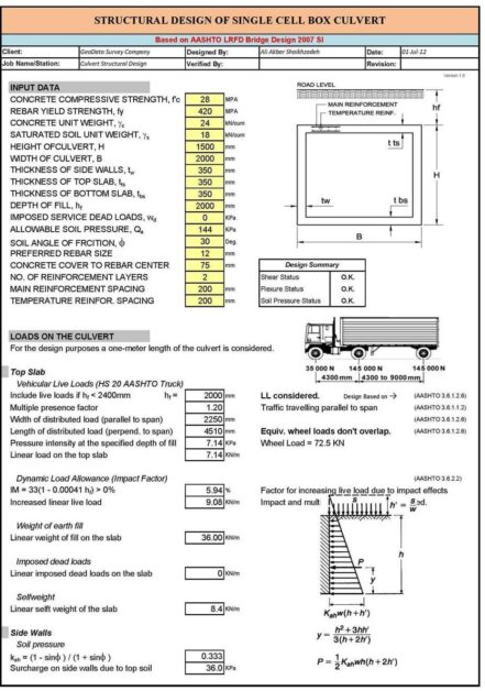
- Home » Excel Sheets » RC Design » Reinforced Concrete » Structural » Excel Sheet Box Culvert Analysis and Design A culvert is a structure that allows water to flow under a road, railroad, trail, or similar obstruction.
New culverts not meeting Design Table requirements and in need of special design. See the Bureau of Local Roads and Streets Manual for guidance on Local Agency culverts. 2.1.3.2 Multi-Barrel Cast-in-Place Concrete Box Culverts For State structures, all new multi-barrel cast-in-place box culverts require a structure number.
There’re bars at 45 degree, known as haunch bars. Wall thickness is 10 inches. Top bar size is #4 @ 6” centre to centre. Bottom bar size is #5 @ 6” centre to centre. Haunch size is #4 @ 12” centre to centre.
Cross-section distribution bars are # 4 @ 12” centre to centre. Vertical bars are # 4 @ 6” centre to centre. Top bars are # 4 @ 6” centre to centre. Bottom bars in bottom slab are # 5 @ 6” centre to centre. Bottom slab is slightly bigger than top slab.
Horizontal length = length – concrete cover
Band is according to slab thickness.
Slab thickness = 10”
Concrete cover (from top and bottom) is 2”
3” band cover is considered

Cut length = length – (2 x concrete cover)

Top bar length = 7.67’

Band = 3”
1’ offset
Concrete cover = 2”
Culvert length = 20’ Box culvert typical section (6 x 7)
r = square root(x2 + y2)
r = square root (1.668 + 1.642)
r = 1.819
Haunch bar total length = 0.5 + 0.5 + 1.819 = 2.819
Numbers = (length – 2 x concrete cover)/spacing + 1
Diameter and length are same in case of distribution bars. [Calculated single time]
Diameter is different in case of top and bottom main bars. [Calculated separately]
Total Length = Bar Length x Numbers x Rows
Weight = d2/52.896
Total Weight = Total Length x Weight/ft
Download Link Excel File
To get more clear idea, go through the following video tutorial.
Lecturer: Civil Gyaan

There are many types of construction available in the construction industry; bridge construction is one of them. It is also a part of structural engineering. Bridge mainly builds on the basis of prior imaginary structure.
There are also different kinds of bridges having different kind of structure. Structural engineers or bridge engineers often face difficulties to design structural elements. It is not always possible to design structures with the help of basic bridge structure software. Here the bridge design and analysis spreadsheet comes in handy for the engineers who are associated with bridge engineering.
To achieve quick summary of divergent sections and parts of diversified bridges, the bridge design excel sheet is made. This spreadsheet is particularly aimed for creating the design of different sectors and elements of bridge in accordance with the necessity of engineers.
Here is an important and beneficial list of excel sheets for engineers and construction specialists.
Precast Box Culvert Design
This bridge design excel sheet contains 11 individual excel sheets which are supported with the most recent codes like ACI, AASHTO LRFD, and so on.
Box Culvert Design Excel Sheet Calculation
The detailed specifications of these spreadsheets are as follows:
Box Culvert Design Excel Sheets
- Bridge Concrete Girder: Prestressed Concrete Girder Design for Bridge Structure supported with AASHTO 17th Edition & ACI 318-11. (Download)
- Bridge Concrete Column: Bridge Column Design supported with AASHTO 17th & ACI 318-11. (Download)
- Bridge Box Section: Bridge Design for Prestressed Concrete Box Section supported with AASHTO 17th Edition & ACI 318-11. (Download)
- Concrete Tunnel: Concrete Tunnel Design supported with AASHTO-17th & ACI 318-11. (Download)
- Double Tee: Prestressed Double Tee Design supported with AASHTO 17th Edition & ACI 318-11. (Download)
- Concrete Box Culvert: Concrete Box Culvert Design supported with AASHTO 17th Edition & ACI 318-11. (Download)
- Steel Road Plate Steel Road Plate Design supported with AASHTO 17th Edition & AISC 360-10 through Finite Element Method. (Download)
- Flange Tapered Girder: Flange Tapered Plate Girder Design supported with AISC Manual 14th Edition (AISC 360-10). (Download)
- Prestressed Concrete Pole/Pile: Prestressed Concrete Circular Hollow Pole/Pile Design supported with ACI 318-11 & AASHTO 17th. (Download)
- Falsework: Falsework Design for Steel Girder Bridge supported with NDS 2012 & AASHTO 17th. (Download)
- Polygon Capacity: Polygon Section Member (Tubular Steel Pole) Design supported with ASCE 48-11. (Download)